
The Mikrotik DHCP Relay Process


Introduction
There appears to be a subtle distinction in how Mikrotik manages the DHCP relay process compared to other vendors such as Cisco and Aruba. Unlike these vendors, Mikrotik sources DHCP Discover and Request packets using the address of the egress interface, rather than the GIADDR/Proxy address
Below is a more detailed explanation of the nuances, including examples.
Cisco
Example Topology
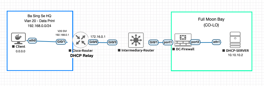
Example Configuration:
interface g0/1.20
ip address 192.168.0.1 255.255.25.0
ip helper-address 10.10.10.2
Process:
Discover ( Router/Relay to Server)
+------------------------------------------------------+
| Source IP: 192.168.0.1 | Dest IP: 10.10.10.2 |
| Source Port: 67 | Dest Port: 67 |
| GIADDR: 192.168.0.1 | CLIENT MAC: |
+------------------------------------------------------+
Offer ( Server to Router/Relay )
+-----------------------------------------------------------------+ | Source IP: 10.10.10.2 | Dest IP: **192.168.0.1** | | Source Port: 67 | Dest Port: 67 | | OFFER: 192.168.0.4 | DHCP SERVER ID | CLIENT MAC | OPTIONS +-----------------------------------------------------------------+
Request ( Router/Relay to Server)
+------------------------------------------------------------+
| Source IP: 192.168.0.1 | Dest IP: 10.10.10.2 |
| Source Port: 67 | Dest Port: 67 |
| Request IP: 192.168.0.4 | DHCP SERVER ID | CLIENT MAC |
+------------------------------------------------------------+
ACK (Server to Router/Relay )
+------------------------------------------------------+
| Source IP: 10.10.10.2 | Dest IP: 192.168.0.1 |
| Source Port: 67 | Dest Port: 67 |
| Client IP = 192.168.0.4 |
| DHCP ID| Options:DNS server, GW, blah blah, |+------------------------------------------------------+
Packet Capture

Mikrotik
Example Topology
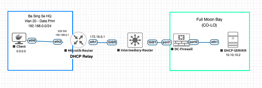
Example Configuration:
/ ip address add address=192.168.0.1
   interface=ether2.20 name=vlan20
/ ip dhcp-relay add dhcp-server=10.10.10.2
   local-address=192.168.0.1 interface=ether2.20 disabled=no
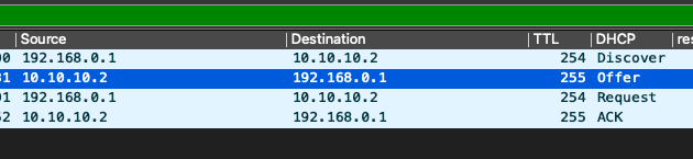
Discover ( Router/Relay to Server)
+------------------------------------------------------+
| Source IP: 172.16.0.1 | Dest IP: 10.10.10.2 |
| Source Port: 67 | Dest Port: 67 |
| GIADDR: 192.168.0.1 | CLIENT MAC: |
+------------------------------------------------------+
Offer ( Server to Router/Relay )
+-----------------------------------------------------------------+ | Source IP: 10.10.10.2 | Dest IP: **192.168.0.1** | | Source Port: 67 | Dest Port: 67 | | OFFER: 192.168.0.4 | DHCP SERVER ID | CLIENT MAC | OPTIONS +-----------------------------------------------------------------+
Request ( Router/Relay to Server)
+------------------------------------------------------------+
| Source IP: 172.16.0.1 | Dest IP: 10.10.10.2 |
| Source Port: 67 | Dest Port: 67 |
| Request IP: 192.168.0.4 | DHCP SERVER ID | CLIENT MAC |
+------------------------------------------------------------+
ACK (Server to Router/Relay )
+------------------------------------------------------+
| Source IP: 10.10.10.2 | Dest IP: 192.168.0.1 |
| Source Port: 67 | Dest Port: 67 |
| Client IP = 192.168.0.4 |
| DHCP ID| Options:DNS server, GW, blah blah, |+------------------------------------------------------+
Packet Capture
Workaround
If you want to force the DHCP process to use the GIADDR/Proxy interface address, instead if the egress interface, you can source nat:
/ip firewall nat add action=src-nat chain=srcnat
 dst-address=10.10.10.2 dst-port=67-68
 in-interface=ether2.20 out-interface=ether1
 protocol=udp src-address=172.16.0.1 to-addresses=192.168.0.1
You would then apply this to other vlans by changing the to-addresses and in-interface parameters to match the other vlans