
Configuring VLTi on Dell Switches

Configuring VLTi
What is VLTi
A layer 2 technology that allows you to stack switches without dedicated stacking cables, The VLT peers (switches running VLT protocol) synchronise protocol state information, MAC address and ARP tables, between them. All VLANs are also automatically allowed on the VLTi link without any manual intervention.
Requirements
1. Each switch should have a port (backup link) for keep alives, and should be in the same broadcast domain
2. Atleast 2 ports (Discovery Interfaces), these are the VLTi links.
3. A VLT domain only supports 2 (TWO) node members
4. Both switches should run the EXACT same OS10 version (even down to the minor and patch)
Caveats:
- Each VLT Domain has a specific MAC addresses
- Each member node has its on Control Plane, (OSPF, STP etc) and Data Plane
- They sync the arp tables etc
- 1 node acts as the Primary and the other the secondary
- Node with the Lowest priority or highest MAC address will be the primary
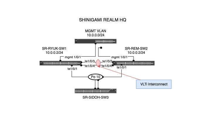
Example Topology
Configuration
SR-RYUK-SW1
Step 1: Configure MGMT Interface
conf t
    interface mgmt 0/0
    ip address 10.0.0.2/24
    end
Step 2: Place Discovery Interfaces in no Switchport
configure terminal
    interface range te1/0/3-4
    description vtli
    no switchport
Step 3: Configure VLT domain
vlt-domain 1
    discovery-interface te1/0/3-4
    backup destination 10.0.0.3
    peer-routing
    primary-priority 4096
Step 4: Configure Port-channel to switch:
configure terminal
    int vlan 10
    ip address 10.10.0.2
    no shut

interface port-channel 10
    switchport mode trunk
    switchport trunk allowed vlan 10
    description Link-to-switch-3
    no shut
    vlt-port-channel 1

#LInk to switch
conf t
    int te1/0/1
    descripton link-to-switch3
    channel-group 10 mode active
    no shut
SR-REM-SW2
Step 1: Configure MGMT Interface
conf t
 interface mgmt 0/0
  ip address 10.0.0.3/24
end
Step 2: Place Discovery Interfaces in no Switchport
configure terminal
 interface range te1/0/3-4
  description vtli
  no switchport
Step 3: Configure VLT domain
vlt-domain 1
    discovery-interface te1/0/3-4
    backup destination 10.0.0.2
    peer-routing
    primary-priority 8192
Step 4: Configure Port-channel to switch:
configure terminal
intface vlan 10
    ip address 10.10.0.3
    no shut

interface port-channel 10
    description link-to-swtich3
    switchport mode trunk
    switchport trunk allowed vlan 10
    no shut
    vlt-port-channel 1

#LInk to switch
conf t
 int te1/0/1
    description link-to-swtich3
    channel-group 10 mode active
    no shut
On Switch 3:
Step 1: Configure vlan 10
int vlan 10
ip address 10.10.0.10
no shut
Step 2: Configure Port channel
conf t
  int port-channel 10
    description link-to-cores
    swithport mode trunk
    switchport trunk alowed vlan 10
    no shut
Step 3: Bind port channel to ports
int range te1/0/1-2
    description link-to-cores
    channel-group 10 mode active
    no shut
Step 4: Testing
ping 10.10.0.2
ping 10.10.0.3
Show commands:
show vlt 1
show vlt 1 vlt-port-detail
show interface port-channel 10
show vlt 1 backup-link
show vlt 1 mismatch
Peer Routing
In a Dell VLT (Virtual Link Trunking) configuration, Peer Routing is a feature that allows VLT peers (two switches in a VLT domain) to route traffic on behalf of each other for Layer 3 routing.
Normally, in a VLT setup, both switches act as a single logical switch for Layer 2 but operate independently for Layer 3. Peer Routing enables them to handle Layer 3 routing as if they were one, preventing the need to send certain types of routed traffic back to the originating VLT peer, which reduces latency and optimizes traffic flow.
Key Points:
- Layer 3 Optimization: VLT Peer Routing improves Layer 3 routing by allowing each VLT peer to route traffic without forwarding it to the other peer.
- Reduced Latency: This feature eliminates the "triangular" traffic flow, where traffic would typically travel back and forth between VLT peers.
- Seamless Failover: If one VLT peer fails, the other can continue routing traffic without disruption.
It's particularly useful in environments where you want high availability for both Layer 2 and Layer 3 without introducing extra hops in the network.